Tag Archives: TRISO

On the anisotropy of pyrolytic carbon

The fuel of the High Temperature Reactor is made of a uranium kernel coated with three layers of pyrolytic carbon (PyC) and one of silicon carbide (SiC). Many times, SiC is regarded as the most important layer in the formation of this type of fuel, without considering the relevance of PyC. Most of the fission products are retained in the kernel and on the pyrolytic carbon coatings. Furthermore, PyC not only avoids the diffusion of elements that otherwise react with SiC and render it permeable but also it confers a higher stability to SiC due to a compressive stress introduced by the shrinkage of this material due to neutron irradiation. In other words without a stable PyC layer, the fuel particle would not be as effective in containing fission products as it is.

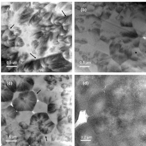
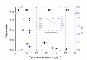
Among the different physical properties of PyC, its anisotropy has been probably the most studied. The term anisotropy is generally referred to the degree of orientation of the graphene planes. It should be mentioned that the value of anisotropy is not constant but depend on the microstructure and the sampling area. Unfortunately, this term has been used many times without considering that anisotropy might refer to different microstructural features depending of the scale length. For example, polycrystalline graphite is made of natural and synthetic graphite, each with a very anisotropic structure (where the graphene planes are well aligned). However, this material is made so the overall structure has a random or isotropic character. Due to the scale length this anisotropy can be described as macro-anisotropy and it is measured by techniques such as X-ray diffraction through the Bacon Anisotropy Factor (BAF). As the length scale is reduced between 0.2 and tens of micrometres, it is possible to measure the anisotropy of individual microstructural features, for example natural graphite (highly anisotropic) in polycrystalline graphite. These are the values obtained with polarised light (Optical Anisotropy Factor, OPTAF) and two modulator generalised ellipsometry (diattenuation and OPTAF), that can scan areas between 2 and 20 µm. For the case of PyC coatings, the values of anisotropy obtained will be affected by the shape of the growth features and the orientation of the graphene planes inside them. As the sampling area is reduced to 0.2 µm or lower it is possible to measure the anisotropy of the graphene planes with little or no effect of the microstructure. These values of anisotropy are obtained with transmission electron microscopy using the selected area electron diffraction patterns. This anisotropy can be referred as nano-anisotropy. Only in the cases where PyC is made of globular features with graphene planes oriented in a circular pattern, the micro- and nano-anisotropy will have similar values (Figure 1). Otherwise, the presence of polyhedral growth features or the orientation of the graphene planes parallel to the deposition plane will produce the deviation between micro- and nano-anisotropy (Figure 2).

Further information can be found here:

E. López-Honorato, C. Boshoven, P. J. Meadows, D. Manara,      P. Guillermier, S. Juhe, P. Xiao, J. Somers. Characterisation of the anisotropy of pyrolytic carbon coatings      and the graphite matrix in fuel compacts by two modulator generallised      ellipsometry and selected area electron diffraction. Carbon 50, 680-688, 2012. http://dx.doi.org/10.1016/j.carbon.2011.09.027

Different growth features in PyC

Figure 1. Different growth feattures in pyrolytic carbon

Relationship between anisotropy diattenuation OPTAF and Orientation Angle OA

Figure 2. Relationship between the anisotropy measured by diattenuation, OPTAF and orientation angle, OA.

The High Temperature Reactor and the TRISO coated fuel particle (Part II)

The inner and outer pyrolytic carbon layers both shrink and creep during irradiation. A portion of the gas pressure (30 MPa for a power of 150 mW/particle) is transmitted through the IPyC layer into the SiC. This pressure continually increases as irradiation of the particle continue, thereby contributing to a tensile stress in the SiC layer. However, countering the effect of the pressure load is the shrinkage of the IPyC and OPyC during irradiation, which pulls the SiC inward. Failure of the particle is normally expected to occur if the stress in the SiC layer reaches the fracture strength of SiC. The pressure induced failure can be reduce by providing an ample margin in the thickness of the buffer layer and by changing the fuel kernel from UO2 to UCO, which would produce a decrease in the amount of CO produced (the main gas responsible for the internal pressure). Pyrolytic carbon cracking can be eliminated by reducing the anisotropy of the PyC layer.

Chemical interaction of the SiC coating layer with fission products is another possible performance limitation of the TRISO-coated fuel particle. Previous irradiation experiments indicate that fission products of palladium and lanthanides react with the SiC layer. Corrosion of the SiC layer could lead to fracture of the coating layers or provide a localised fast diffusion path, which degrades the capability of retaining fission products within the particle. The corrosion of SiC by the fission product palladium has been observed in almost all kinds of fuel compositions, and is considered as one of the key factors influencing the fuel performance. To avoid the degradation of the coating layers caused by extensive corrosion of the SiC layer, it is necessary to limit the fuel temperature, irradiation time or increase the thickness of the SiC layer. These limitations narrow the range of operation conditions of the HTRs.

Although not a failure mechanism, the migration and release of silver (produced by the decay of Uranium) is considered an important issue since it determines the plan maintainability and service requirements. Silver can migrate through intact particles and be released into the reactor coolant system, where it will deposit on cold surfaces. Even though the release mechanism is not very well understood, it has been demonstrated that silver diffuses through the grain boundaries in SiC (Fig. 1)

Fig. 1. Silver diffusion in SiC. E. Lopez-Honorato et al. Silver diffusion in silicon carbide coatings. J. Am. Ceram. Soc. 94, 3064-3071, 2011. http://onlinelibrary.wiley.com/doi/10.1111/j.1551-2916.2011.04544.x/abstract

Challenges for future Nuclear Reactor Systems (Part II)

High Temperature Reactors

Commercial reactors generally operate with an outlet temperature of around 200-300°C with the heat produced only used to generate electricity. By contrast, considerably higher temperatures (800-1000°C) can be achieved in a new generation of nuclear reactors known as High Temperature Reactors (HTR). The high temperature reactor is a particularly intriguing reactor system with exceptional safety characteristics combined with high efficiency for conversion of heat to electricity. Furthermore, direct use of the heat produced, via a heat exchanger, are envisaged also for industrial processes. For example, above 400°C the heat generated can be coupled for iron manufacturing and petrochemical processes such as the de-sulfurisation of heavy oil, petroleum refining and production of ethylene and styrene (Fig. 2). One very important product that can be obtained using the heat from a HTR is hydrogen. This element, considered essential for the future transport industry and currently used to produce liquid fuels, ammonia, methanol and other products, is presently obtained from a process called steam methane reforming. In this method, steam and methane are combined to produce hydrogen and CO2, using heat from natural gas. The heat produced by the HTR not only could replace the use of natural gas but also can be used to directly split water to produce H2 and O2 without the necessity to convert large amounts of carbon to CO2. The use of this technology could further reduce green house emissions by replacing the large amount of fossil fuels used today for industrial processes.

Figure 2. Nuclear process heat for the industry. http://www.nextgenerationnuclearplant.com/

 The safety of a HTR originates from the characteristics of its fuel and the design of the core. The fuel of the HTR is made of a very small fuel particles (0.5 mm in diameter) covered by four thin layers of ceramic making it no larger than 1 mm (Fig 3). Thousands of this particles, known as TRISO fuel, are then mixed with graphite to make the fuel elements in spherical (pebble bed design) or cylindrical (prismatic core) form depending on the design of the core. One of the main advantages of this type of fuel is that the thin ceramic coatings (aprox. 0.03 mm in thickness each) serve as a miniature fission product containment vessel designed to trap all the fission products. Under off-normal conditions, the fuel in a reactor with a power of less than 200 MW rises to less than 1600°C, and the integrity of the ceramic components is maintained.

Figure 3. The components of the pebble fuel in the High Temperature Reactor. http://www.pbmr.com

Super Critical Light Water Reactors

The supercritical light water reactor (SCLWR) is perhaps more appropriately referred to as the high performance light water reactor (HPLWR). Like the light water reactor (LWR), its coolant is water, but it is maintained under conditions where water becomes a so called super critical fluid. Thus, its characteristics change dramatically. The main advantage of this concept lies in the higher efficiency, with which the heat can be converted to electricity. With a 50% higher efficiency than a conventional system, a major impact on the system economy can be achieved. Furthermore, this leads to a concomitant decrease in the waste generated.

Molten Salt Reactors (MSR)

The final reactor selected is cooled by a molten salt. The salts are mixtures are based on lithium and sodium fluorides (LiF and NaF), which depending on their composition melt at around 700°C. The fuel is also in the form of a fluoride and is dissolved in the molten salt. Unlike all the other reactor systems, the fuel is not static. It is pumped through the reactor core, and is “cleaned” of its impurities (i.e. fission products) in an online treatment facility. This reactor exhibits great flexibility in its operation, and furthermore can be readily fuelled in a sustainable manner by thorium, an element even more predominant than uranium in the earths crust. Challenges lie in the fuel chemistry, separation technologies, and in the qualification of materials resistant to the corrosive molten salts.

The path forward

Current reactor technology will continue to play an important role. The majority of the reactors operating today belong to Generation II light water reactors (LWR). Newest LWR reactors (Generation III) have adopted additional safety technologies.

Safety of the reactor operation is essential no matter what reactors are deployed. The quest for perfection is unremitting. It can cover core design and layout. The behaviour of the fuel with its inventory of fission products during normal and off normal reactor operating conditions, during interim storage (cooling) and reprocessing, and indeed within a long term repository must be known and quantified.

Licensing by national authorities, often known as technical safety organisations (TSOs), is essential. The light water reactor fleets have generated a large quantity of operational experience and data, enabling the establishment of engineering based computer simulation codes, with sufficient predictive capability for licensing. Establishing this competence for future reactor systems will require a similar engineering type effort. Science never stands still. However, theory is developing fast, as is computational power. Though still a fair way off, it can be expected that a paradigm shift for licensing will occur. Improved computational power and modelling will lead to advanced designs, and improved less time consuming and costly paths to best possible fuels.

The recent events at Fukushima will reinforce nuclear industry’s commitment to safety. The unimaginable must be imagined, and measures taken to contain consequences of a plant failure, as successfully achieved at Three Mile Island in 1979.